

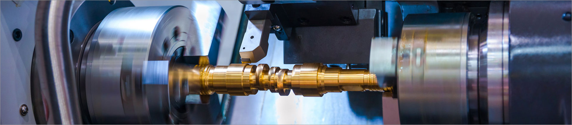

How CNC Robot Loading and Unloading Automation Works for CNC Machine Tending
CNC robot loading and unloading automation works by coordinating a robot, workholding, machine controls, and safety systems to move parts into and out of a CNC machine. The robot presents a raw workpiece to the fixture, confirms that the machine is ready, and loads the part; after machining, it removes the finished part and places it in a designated location. The machine and robot exchange signals at each stage so that the door, chuck, and robot movements follow an agreed sequence.
If you want to learn more, please visit our website.
For manufacturers, the goal is not simply to add a robot beside a machine. A reliable tending cell must match the part, cycle, fixture, operator workflow, and available floor space. Below, we explain the process step by step, highlight key design decisions, and share practical ways to avoid common integration problems.
Key Takeaways
- A CNC tending cell links robot motion with machine-ready, door, chuck, and cycle signals.
- Part presentation, gripping, and fixture access need to be designed together.
- Cycle timing, safe operation, and recovery procedures should be validated before production.
- Successful automation starts with accurate part and machine information, not a robot specification alone.
What Happens During CNC Machine Tending?
Machine tending is the repeated handling of workpieces around a manufacturing machine. In a CNC application, the robot typically transfers raw stock from a tray, conveyor, or other supply point to the machine fixture, then moves machined components to an output location. Depending on the process, it may also perform tasks such as part orientation or a defined check before loading.
The cell may include a robot, gripper, part storage, safety guarding or other protective measures, and an interface with the CNC. The exact arrangement depends on machine access, part geometry, required production flow, and the level of automation. Some systems serve one machine, while a properly engineered layout may be designed to tend more than one machine.
Step-by-Step: How the Automation Cycle Works
1. Prepare and identify the workpiece
Before a cycle begins, parts must be available in a repeatable position. A tray, rack, conveyor, or custom fixture can present blanks so the robot can pick them consistently. The cell design should account for part orientation and variation, since a robot cannot reliably grip a part that arrives outside the expected pickup position without an appropriate detection or locating method.
2. Confirm that the CNC is ready
The robot does not simply enter the machine whenever it chooses. The machine and robot exchange status signals so the sequence can confirm that machining has ended and that the machine is in a condition for tending. The specific signals and control logic vary by CNC model and integration design, so they should be agreed upon and tested during commissioning.
3. Access the machine safely
Once the required conditions are met, the system provides access to the machine, often by commanding an automatic door where the equipment supports it. The robot follows a programmed path into the work area while respecting the designed safety conditions. Door control, robot access, and machine state must be coordinated to prevent conflicting actions.
4. Remove the finished part
The robot approaches the fixture and grips the completed component. The gripper may be mechanical, pneumatic, or another suitable design, depending on the workpiece and process requirements. The system must account for gripping access, chip and coolant exposure, and the possibility that the part may not be seated or released as expected.
5. Load the next blank and confirm the setup
After removing the finished component, the robot places a new blank into the machine fixture. The fixture and gripper must allow the part to reach the required position without collision or obstruction. Where the process requires it, the cell can include a defined check for part presence or seating before the CNC cycle is allowed to start.
6. Return the finished part and restart machining
The robot places the completed component in an output location, such as a tray or conveyor, then moves out of the machine envelope. The system confirms that the robot is clear and that required conditions are satisfied before the CNC begins the next program cycle. The sequence then repeats, with operators replenishing raw stock and removing finished parts according to the cell’s workflow.
If you want to learn more, please visit our website Yinglai Technology.
Key Decisions When Designing a Tending Cell
Match robot reach and payload to the real task
Robot selection should consider the complete path from the pickup point to the machine fixture, not just the distance to the CNC door. Payload calculations need to include the gripper and any tooling as well as the workpiece. For a preliminary layout discussion, a buyer might document an illustrative 2 kg workpiece and an 800 mm required reach; these are example inputs only, not recommended specifications for every cell.
Choose a gripper and presentation method together
A gripper must hold the part securely while leaving access to the machine fixture and avoiding interference with nearby features. Raw and finished parts may have different gripping requirements, which can lead to a dual gripper or a tool-change approach, depending on the application. Part trays should also support repeatable pickup and practical replenishment by operators.
Check cycle time and machine access
The robot’s handling sequence must fit the production process, but the actual benefit depends on the complete cycle rather than the robot’s travel time alone. Door movement, part exchange, clamping, machining, and any inspection steps all contribute to the workflow. Measure the current process and agree on the required tending window before finalizing the automation concept.
Design for safe operation and recovery
Safety provisions depend on the application, layout, equipment, and applicable requirements. The cell should define how operators replenish stock, remove output, respond to a fault, and regain a safe operating state. Recovery steps matter because an automation system must be maintainable in everyday production, not only during an uninterrupted cycle.
Common Mistakes to Avoid
- Specifying the robot before checking access: Confirm the machine door, fixture position, and approach path before choosing reach and mounting position.
- Ignoring part variation: Evaluate blank tolerances, orientation, and presentation so the pickup method fits actual incoming conditions.
- Planning only for ideal cycle time: Include door operation, clamping, changeover, stock replenishment, and normal recovery in the process review.
- Leaving signal ownership unclear: Define which system controls each action and how the CNC and robot verify that the next step is permitted.
- Overlooking operator tasks: Plan where raw material and finished parts go, and ensure routine replenishment fits the available workspace.
How to Improve Reliability and Production Flow
Start with a clear process map that shows each machine state, robot action, and confirmation signal. Review the sequence with the CNC and automation teams so they can identify missing conditions before programming and installation. A simple example inventory input might be a six-part buffer, but the right quantity depends on part size, replenishment frequency, and available space.
Next, test the full handling path using the actual workpiece or a representative part. Check grip security, fixture access, chip and coolant exposure, and the placement of both input and output stock. If the product family includes multiple part types, identify which elements can be shared and which require a different gripper, fixture, program, or setup procedure.
Finally, define how the cell will communicate faults and resume operation. Useful design discussions include what happens when a part is missing, the gripper fails to confirm a hold, or the CNC is not ready. Clear operator instructions and a practical recovery sequence help make the system easier to run and support.
How Yinglai Technology Can Support Your Project
Yinglai Technology works with manufacturers seeking CNC robot loading and unloading automation for machine tending. The project discussion can begin with your CNC model, part drawings, workpiece mass and dimensions, current cycle, and production goals. This information helps establish whether the concept needs a robot, suitable gripping, part presentation, machine communication, and a cell layout matched to the application.
Before requesting a proposal, prepare photos or layout drawings of the machine area, details of the fixture and door access, and an outline of operator material-handling tasks. Share the expected part range and any changeover requirements as well. These inputs help suppliers assess the application and clarify open technical questions before the design is finalized.
Conclusion: A Coordinated Process Makes CNC Tending Work
CNC robot loading and unloading automation works by coordinating part supply, robot handling, machine access, fixture loading, and CNC cycle signals in a controlled sequence. The most important next step is to document your part, machine, cycle, and operator requirements before selecting equipment. Contact Yinglai Technology with these details to discuss a tending concept suited to your CNC application and production workflow.
Comments
All Comments ( 0 )