

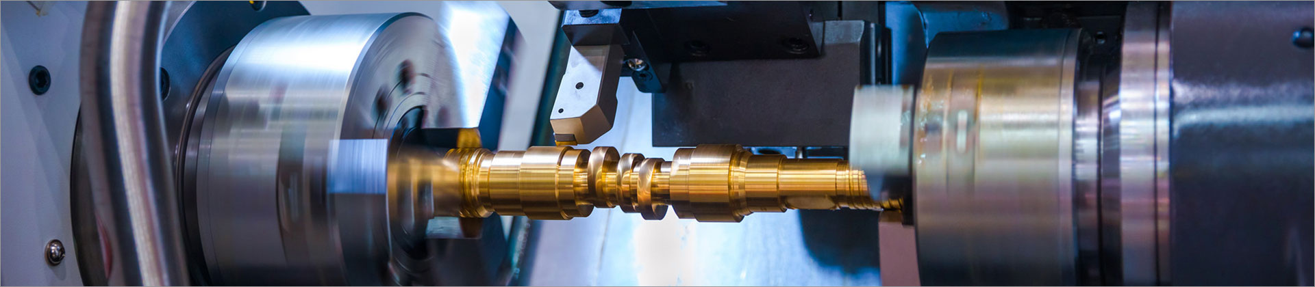

Form Milling Cutter Selection Guide: Types, Applications, and Key Specifications
Choose a form milling cutter by matching its cutting profile to the part geometry, workpiece material, machine setup, and required tolerance. The cutter may be a standard profile tool or a custom-ground design, and its substrate, coating, dimensions, and flute geometry all affect suitability. Before requesting a quotation, provide a part drawing, material and hardness, machine details, and expected production volume. At LZQ, we use those details to understand the application and discuss a suitable cutter specification rather than treating the tool as a one-size-fits-all item.
Key Takeaways
- A form milling cutter creates a defined contour or shaped feature in one or more machining passes.
- Profile geometry, workpiece material, rigidity, and required surface quality should guide cutter selection.
- HSS, solid carbide, and carbide-tipped designs suit different operating conditions and purchasing priorities.
- For a useful supplier quotation, share a drawing and clarify tolerances, quantity, and delivery requirements.
Who This Guide Is For
This guide is intended for procurement teams, manufacturing engineers, toolroom managers, and distributors sourcing form milling cutters for production or maintenance. It is useful when evaluating a standard cutter, replacing a worn tool, or asking a supplier to develop a custom profile. The guidance is general: the correct geometry and cutting conditions depend on the specific tool, machine, workpiece, and operation.
What a Form Milling Cutter Does
A form milling cutter has a cutting edge shaped to produce a corresponding profile on a workpiece. Depending on the design, it can machine features such as radii, grooves, concave or convex contours, and other defined outlines. The profile may be produced in one pass when the tool and setup allow, or through multiple passes when access, chip evacuation, or machine capacity requires a different approach.
Unlike a general-purpose end mill, a form cutter is selected around the shape it needs to generate. The cutter profile, mounting arrangement, and machining path must all be considered together. A profile drawing is therefore more useful than a verbal description alone, especially when several radii, steps, or transitions need to be controlled.
Types and Material Options
Common Form Cutter Designs
- Concave and convex cutters: Used to machine corresponding curved profiles, subject to the required radius and tool access.
- Radius and corner-form cutters: Used where a defined edge radius or rounded feature is required.
- Custom-profile cutters: Ground to a drawing when the contour is not covered by an available standard design.
- Solid or mounted designs: The appropriate construction depends on cutter size, machine interface, and the application’s rigidity requirements.
Tool Material and Coating
High-speed steel (HSS) can be considered for applications where toughness, cutting conditions, or cost make it appropriate. Solid carbide is often evaluated for higher-hardness materials, demanding wear requirements, or setups that can support a more rigid tool. Carbide-tipped constructions may be relevant for some larger or specialized cutters, but the best choice depends on geometry and operating conditions rather than material name alone.
Coatings can influence wear behavior and heat management, but no coating is universally best. Discuss the workpiece material, coolant practice, cutting speed, and expected tool life with the supplier. If you are changing from an existing cutter, provide its material and coating details when known so the comparison is more meaningful.
Match the Cutter to the Application
Start with the feature to be machined and identify whether it is an internal contour, external contour, groove, or edge form. Check whether the cutter can reach the feature without colliding with the fixture or adjacent surfaces. Also consider how chips will leave the cutting zone, particularly in deep or enclosed features.
For repeat production, profile consistency and tool life may carry more weight than the lowest unit price. For short runs or maintenance work, availability and compatibility with existing holders may be more important. In either case, confirm that the machine can provide the required spindle interface, power, rigidity, and workholding support.
You will get efficient and thoughtful service from LZQ.
Key Specifications to Confirm
| Specification | Why It Matters | What to Provide or Confirm |
|---|---|---|
| Cutting profile | Defines the geometry produced on the part. | Drawing, CAD data, profile radii, and critical dimensions. |
| Diameter and cutting width | Affects access, clearance, and tool-path planning. | Required dimensions and machine or holder limits. |
| Material and coating | Influence wear behavior and suitable cutting conditions. | Workpiece grade, hardness if known, and coolant practice. |
| Shank or arbor interface | Must match the machine setup and provide secure mounting. | Interface type, size, and available holder details. |
| Tolerance and finish | Determine inspection needs and manufacturing requirements. | Critical tolerances, surface-finish target, and inspection method. |
Use numbers as drawing requirements, not as assumptions about every cutter. For example, a part drawing might specify a 10 mm radius, while a buyer could request a ±0.02 mm profile tolerance for a particular feature. These are illustrative values only; feasibility should be confirmed against the cutter design, material, setup, and inspection method. Similarly, a design with 2–6 flutes may be encountered across milling tools, but the appropriate flute count for a form cutter depends on its geometry and application.
A Practical Selection Framework
1. Define the Part Requirement
Identify the exact contour, critical dimensions, tolerances, and finish requirements. Mark which surfaces are functional and which are non-critical. If the drawing does not show enough detail to define the cutter profile, provide a model or request clarification before tool manufacture.
2. Describe the Machining Setup
Share the machine type, spindle or arbor interface, available tool clearance, workholding method, and whether the operation is roughing, finishing, or both. Include the workpiece material and hardness when available. These details help the supplier assess tool construction and highlight potential access or rigidity concerns.
3. Compare Standard and Custom Options
Ask whether a standard profile can meet the part requirement before commissioning a custom cutter. A standard tool may reduce development requirements when its geometry and dimensions match. A custom tool may be necessary when the profile is unique, but it should be specified from an approved drawing and agreed inspection criteria.
4. Confirm Commercial Requirements
Request pricing against the required quantity and clarify whether the quotation covers tooling, inspection documentation, packaging, and shipping. Minimum order quantity and lead time vary by design, material availability, production schedule, and order size. For a new or custom tool, ask the supplier to confirm the expected process and timing in the quotation rather than relying on a generic estimate.
Supplier Evaluation Checklist
- Can the supplier review a drawing or CAD file and identify missing specification details?
- Will the quotation state the cutter material, dimensions, interface, and profile requirements?
- Can the supplier explain how the proposed design relates to the workpiece and machine setup?
- Are inspection expectations, packaging, MOQ, and lead time clearly discussed?
- Is there a process for handling drawing revisions or changes to the application?
Clear communication is especially important for custom profiles. Agree on the drawing revision, units, critical dimensions, and acceptance method before production begins. If the cutter is intended to replace an existing tool, photos and measured dimensions can support the review, but they should not replace a controlled drawing where precise geometry is required.
Common Selection Mistakes
- Ordering from a profile name alone: Similar names can refer to different geometries; verify the drawing.
- Ignoring machine clearance: A cutter may match the profile but be unsuitable for the available access or holder.
- Choosing only by purchase price: Consider quantity, expected use, compatibility, and the cost of tool changes or downtime.
- Leaving tolerances ambiguous: Identify the dimensions that matter and how they will be inspected.
Work with LZQ on Your Cutter Requirement
At LZQ, we support B2B buyers evaluating form milling cutter requirements by reviewing application details and discussing relevant product specifications. To begin, prepare your part drawing or profile, workpiece material, required quantity, machine interface, and target delivery schedule. If some information is not yet available, share what you have and identify the open points so they can be clarified before quotation.
Conclusion
The right form milling cutter is the one that matches the required profile and can be used reliably within the limits of the workpiece, machine, and production plan. Confirm the cutter geometry, material, dimensions, interface, tolerance, and commercial terms before placing an order. For a practical next step, send LZQ your drawing and application details to discuss whether a standard or custom form milling cutter is the better fit.
Comments
All Comments ( 0 )